What is FIFO Clock?
FIFO Clock is an open-source digital clock similar to a binary clock or the TIX Clock that displays the time using discrete LEDs.
FIFO stands for First-In First-Out, which refers to the way time is shown using LEDs as described below.
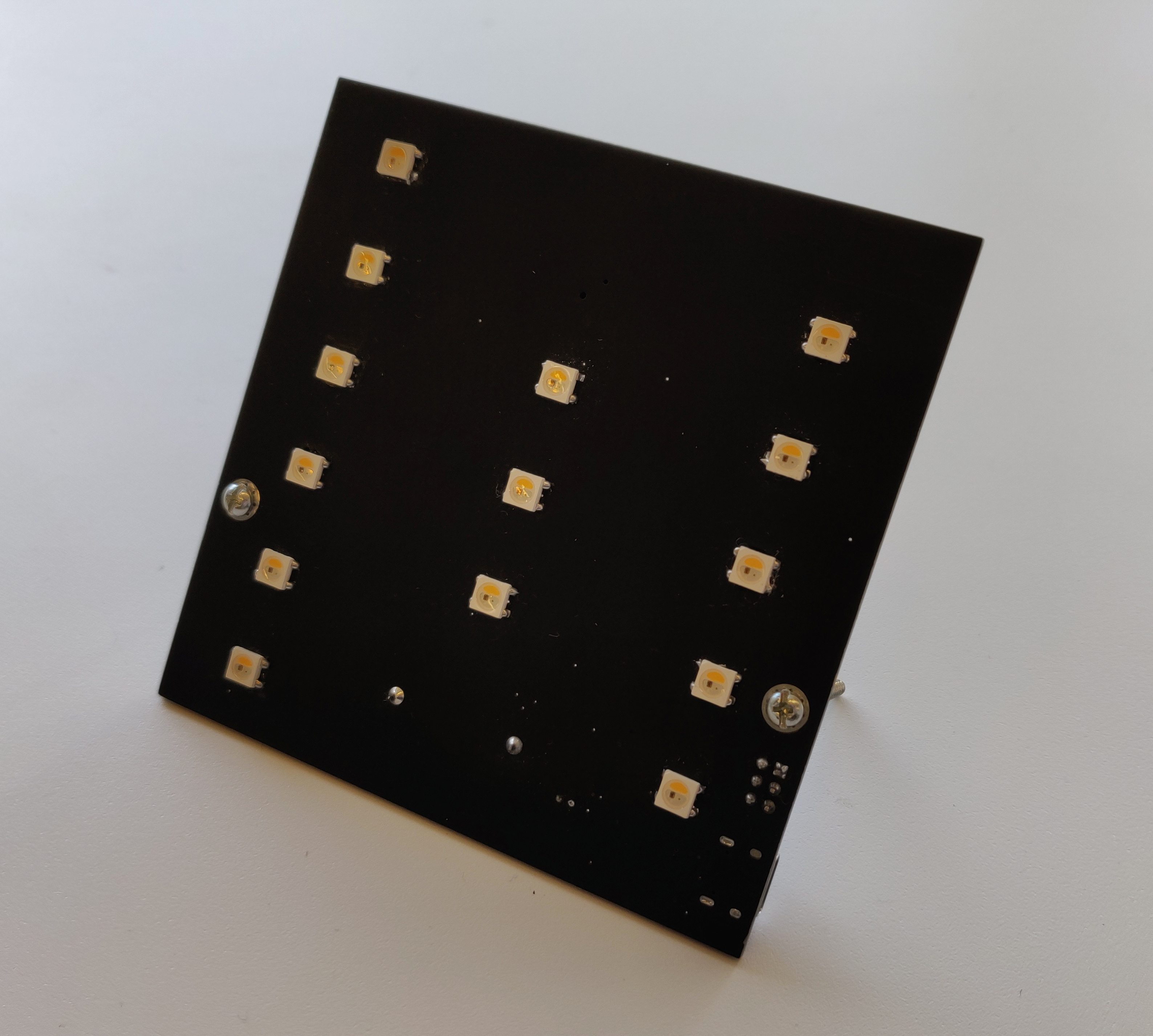
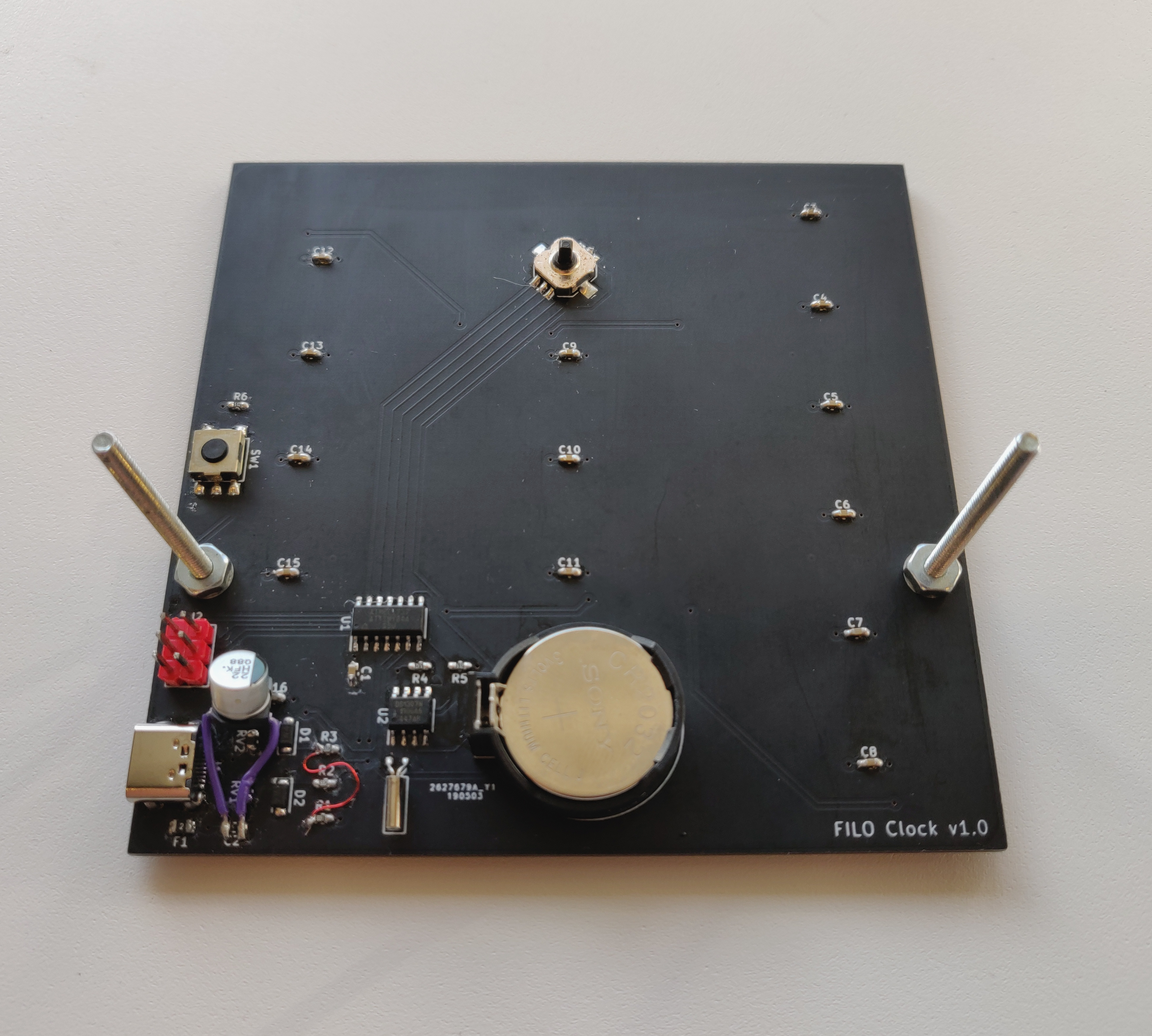
Pictures
About Us
We are Connor Northway and Eddie Zhou, two second-year Computer Engineering and Computer Science students at Northeastern University (as of Jan. 2020).
Device Specifications
Hardware
- Microcontroller - ATTiny84
- Real Time Clock (RTC) - DS1307
- Individually Addressable RGBW LEDs - 14x SK6812
- USB Type-C
- CR3032 Battery Backup for RTC
- Joystick for on-clock settings
Software
- Arduino-compatible firmware
- USB 1.1 via Micronucleus
Inspiration
We were inspired to create our own clock by this Smarter Every Day video. The idea for the FIFO Clock started as a compromise between a binary clock and the TIX Clock. Unfortunately the original version of the TIX Clock is no longer made, but check out the TIX Clock II if you want to buy one.
The FIFO system for our clock is a way of representing a numerical digit using individual LEDs. It was created as a compromise between the TIX Clock’s system of counting illuminated LEDs and binary clocks. FIFO uses half as many LEDs as the TIX Clock, while being faster and easier to read than a binary clock.
How to Read the FIFO Clock
The clock shows the time using three columns of LEDs:
- 6 LEDs on the left to represent the hour
- 3 LEDs in the middle to represent tens digit of minutes
- 5 LEDs on the right to represent the ones digit of minutes
- Each column of LEDs starts with all LEDs off, representing the number 0 (12 for the hours column).
- To count up, LEDs are sequentially turned on from the bottom up until all LEDs in the column are illuminated.
- To continue counting up, LEDs are turned off from the bottom up until all LEDs are off again.
(Each column can represent twice as many values as the number of LEDs!)
Here are some examples of various times:
To quickly calculate a digit when the LEDs are at the top of a column, one of these formulas may be useful:
- (Total Number of LEDs in Column) + (OFF LEDs)
- 2 * (Total Number of LEDs in Column) - (ON LEDs)
Build Guide
Tools
- Soldering Iron (with temperature control)
- Solder
- Flux
- Tweezers
- Desoldering Wick
- Multimeter
- Magnifying glass or microscope
What you’ll need
PCB: Gerber Files
You can download these and send them to a number of PCB manufacturers (JLCPCB, PCBWay, etc)
For a detailed list of components with part numbers and ordering links see: Bill of Materials
We purchased most of our components from LCSC, and the LEDs from AliExpress.
Other hardware you’ll need to complete the clock:
- USB-C Cable
- CR2032 Battery
- 2x M3 Screws (about 40mm length)
- 2x M3 Nuts
The M3 hardware can be replaced by 6/32 imperial hardware.
Soldering
This project involves quite a few small SMD components. If you don’t have much experience with SMD soldering, check out the EEVBlog’s excellent video on the subject.
Components are listed on the BOM with their reference designator, which can be matched to the silkscreened text on the PCB.
Step 1 - LEDs
Solder the SK6812 LEDs to the front. They are oriented so that the warm white portion points toward the top of the clock (the corner notch will be in the top left). Past v1.1 there should be a silk-screened corner to align them.
The LEDs are somewhat thermally sensitive, so try not to heat them for too long or you may end up with strange issues later.
Step 2 - SMD
Solder the high pin count SMD components to the back. This includes the USB-C connector, ATTINY, and DS1307. This way, other components won’t be in the way of these more difficult components.
Next, do small passives (resistors and capacitors).
Lastly, solder the reset button and joystick.
WARNING: The joystick’s internal plastic structure is easily melted when attempting to fix soldering mistakes, which will lead to a stuck switch! Be careful and do not apply heat for long periods of time.
Step 3 - Through-Hole
Finally, solder the through-hole components, including the battery holder, RTC crystal, and programming header.
Firmware Installation
(Note: These instructions are for Linux-based systems, and may need some modification to work on Windows/MacOS)
Setting up Tools
To flash the initial micronucleus bootloader, you will need an in-circuit serial programmer (ISP). The easiest option is to set up an arduino board to act as one. Instructions for doing so can be found here.
Next, you’ll want to install avrdude (which should be in your distribution’s
repositories) and micronucleus, which can be cloned from its github repo
here. You’ll need to run
make; sudo make install to make and install the commandline tool. avrdude
will be used to install the bootloader, and micronucleus will be used to
program the clock through USB.
Now that all the necessary tools are installed, clone the firmware repo.
Note: this next step is only needed if you want to customize the bootloader. Otherwise, you can just use the boot.hex provided in our firmware repo.
Building the Bootloader (Optional)
Copy the fifo-default folder into the firmware/configuration
folder of the micronucleus repository you cloned earlier. Then run
make clean; make CONFIG=fifo-default to create the .hex file.
Flashing the Bootloader
Once you have the bootloader .hex made and the ISP connected, run the following command to flash the bootloader:
avrdude -c arduino -p t84 -P \<programmer serial port\> -b 19200 -U flash:w:\<path to fifo bootloader\>
where <programmer serial port> is the serial port of the programmer
(/dev/ttyACM0 in my case) and <path to fifo bootloader> is the path to the
bootloader .hex file.
Setting up the Arduino IDE
Install the Arduino IDE if you haven’t already.
Open the preferences window, and click the button next to “Additional Boards
Manager URLs”. Paste the following URL in and accept the changes
https://raw.githubusercontent.com/fifoclock/board-definitions/master/package_fifoclock_index.json.
In the Arduino IDE, select Tools > Board > FIFO Clock.
To compile the micronucleus programming tool, run make in the micronucleus/command
folder that you downloaded earlier. Copy the micronucleus executable to
~/.arduino15/packages/fifoclock/tools or wherever your .arduinoXX folder is.
To compile the FIFO Clock firmware you’ll also need the TinyWireM, TinyRTClib, and
Adafruit NeoPixel libraries which can be installed using the library manager in the
Arduino IDE: Tools > Manage Libraries....
Uploading Firmware
Open firmware/FIFOClockFirmware/FIFOClockFirmware.ino using the Arduino IDE
from the firmware repo you downloaded earlier.
Connect the FIFO Clock using a USB-C cable, and click upload. Press the reset button on the back of the clock, and wait for the firmware to upload.
Congratulations! You now have a fully functional FIFO Clock!